Building Your Vibrating Belt
Introduction
With the goal of improving the quality of life of people with visual impairment and helping their mobility through a better perception of the environment it was created a tactile belt. Capable of working with different intensities, the tactile belt makes the user perceive, through vibrations, the approaching of an object. In this manual there’s everything you need to know to build you own vibrating belt. You’ll learn how to manufacture your belt, how to assembly the parts and how the hardware and the firmware work.
Manufacturing
The belt hardware basically is composed by 12 haptic motors, an arduino nano, a PCB shield and bypass connectors.
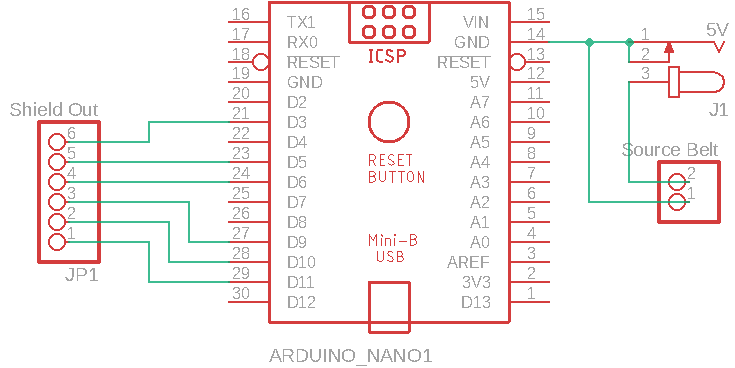
If you want to manufacture the PCB shield you will find all the information you need (PCB design, schematic, eletrical diagram, BOM file) in the Vib-belt Repository. The PCB schematic is shown in the image bellow.
Assembly
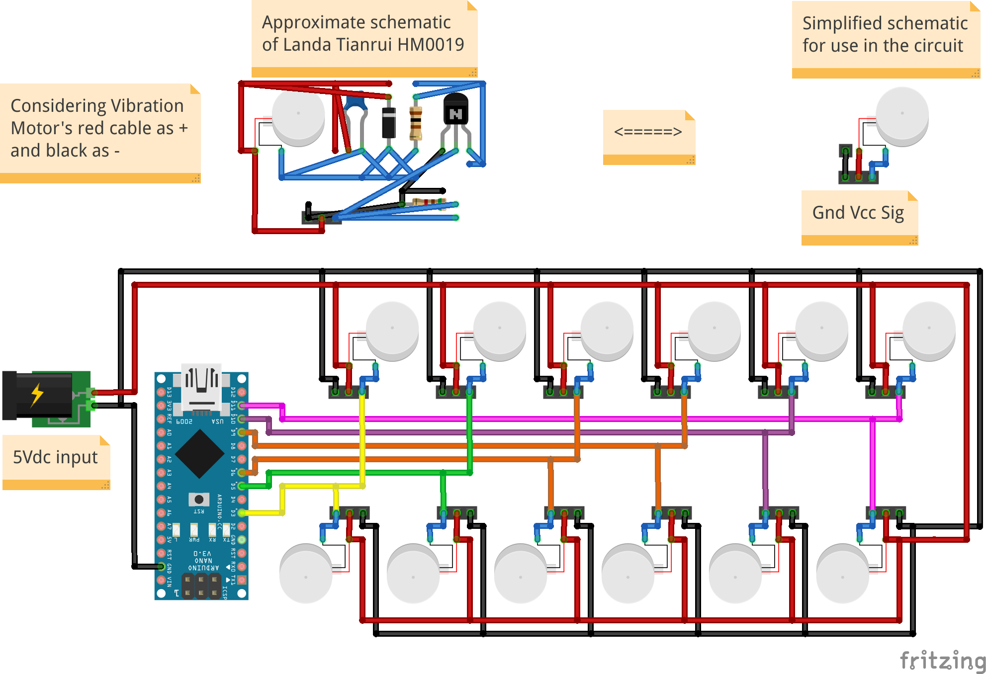
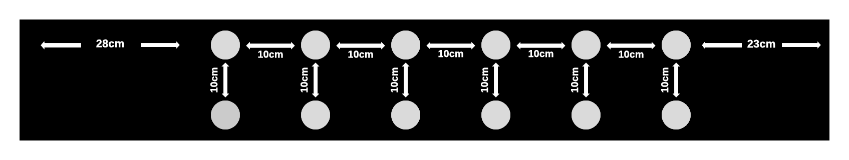
The belt has 2 motor vibracall MV50 modules in each of its 6 columns. These modules have three wires connected to them (Gnd, Vcc-5V and the command sign). To connect the wires to the modules we recommend that you use bypass connectors. The modules are spaced 10cm of each other in the two directions. The image shows exactly how to organize the modules in the belt.
The image bellow shows how to assembly the parts of the belt. If you prefer, the Fritzing file is also avaliable for you.