Arduino
Arduino Firmware
Firmware Overview Section
To make your robot work you’ll need to download the .ino file and upload it into the arduino.
Before explaining how the arduino firmware arrangement works, it’s important to learn a little about where the firmware takes place throughout the project. There is the high level language called GoDonnie, which connects with the Stage and the simulated robot or with the physical robot. When this connection is established with the physical robot the Raspberry Pi, that communicates with the language, translates the high level commands into lower level commands and then sends them to the arduino. The arduino, in turn, commands directly the sensors and the actuators of the physical robot.
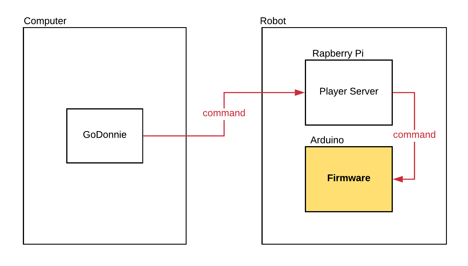
The firmware is the code that intermediate between the GoDonnie language and the hardware device, and it runs in the arduino. The arduino firmware it’s directly connected with the Raspberry Pi, which sends commands to the arduino that causes the motors to move and the sensors to function. Shortly thereafter the arduino sends back to the Raspberry Pi the information obtained by the sensors. The Player server runs in the Rasp, which is connected with the GoDonnie through the computer. The robot’s camera is also connected through the Rasp, that receives the image from the camera and sends to the Player, which processes the images.
Detailed Firmware Section
- Special Bytes Definition
Some bytes have a special meaning at certain points within a packet. These are given symbolic names as follows.
SYNC0   0xFA
SYNC1   0xFB
END     0xFE
ARG     0x3B
NARG    0x1B
SARG    0x2B
When integers are sent as arguments, they are always inserted into the byte stream as 2 bytes. The first byte is the low byte, the second byte is the high byte of the integer.
- Packet Protocol
The protocol is based on command packets that are sent to the controller, and information packets that are received by the host PC. All packets have the following format.
SYNC0
SYNC1
count
count-2 bytes of data
checksum (1 byte)
- Checksum Calculation
The checksum is calculated on the full packet. The checksum algorithm is given here
in C code. The argument size is the number of bytes, and *msg is the vector
of bytes in the packet. This checksum algorithm is based on the CRC8 formulas
by Dallas/Maxim.
uint8_t Player::checksum(const uint8_t *msg, uint8_t size) {
    uint8_t crc = 0x00;
    while (size--) {
        uint8_t extract = *msg++;
        for (uint8_t tempI = 8; tempI; tempI--){
            uint8_t sum = (crc ^ extract) & 0x01;
            crc >>= 1;
            if (sum) {
                crc ^= 0x8C;
            }
            extract >>= 1;
        }
    }
    return crc;
}
- Arduino-based Firmware
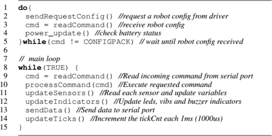
The main loop in the image above (lines 8 to 15) performs the robot control. It initially reads incoming packets from the serial port (line 9), executes the commands (e.g. move commands, line 10), updates the sensor readings into the internal memory (line 11), updates the indicators (LEDs, buzzer, vibration motors) based on the command and sensor readings (line 12), and sends the new data via serial port to the Player Driver (line 13). The last line updates counters that control the frequency to send the serial messages.
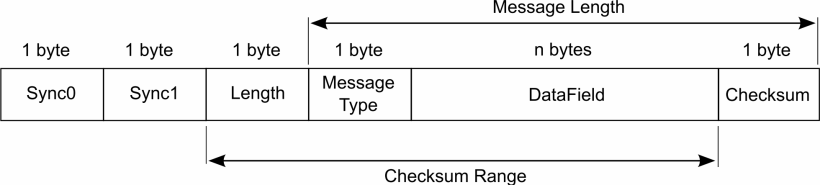
The Enlace-level of the serial messages presented in figure below has two constants bytes of header, one byte of packet length, one byte for message types, variable number of bytes for the payload, and a final byte with checksum. Each functionality in the Arduino board has a corresponding message type.
When the user adds a new functionality to the robot, he/she has to define a new message type and adapt both the firmware and the driver to handle this new message. The firmware and driver codes have comments to give clues to the user as in where to change.