Building Donnie Robot Environment
Braille Cell Manual
Drawing the Parts
The panels and braille cells production process starts with they being drawn in the CAD Corel Draw® software. The drawn pieces can be divided in three types:
- Braille Cells fixation panel
- Braille cell for pin insertion that compose the representation in braille of letters, numbers and symbols.
- Pins that are used for insertion in the braille cells.

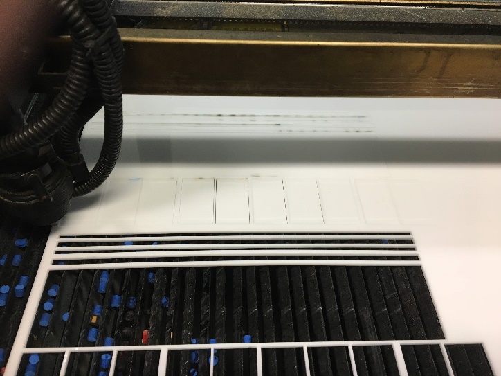
Cutting the Parts
The second stage of the production process is the laser cutting. In our production we used a laser cutting machine model CMA1080. The cutting of each of the three parts can be seen in the images bellow.
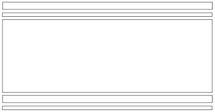
Braille Cells fixation panel:
This panel was made with 3mm thick milky white acrylic. Two grooves were made in the edges so the braille cells could move through the fixation panel. This fixation panel can be made as large as necessary, in this case we used the size to support up to ten braille cells.
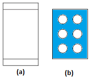
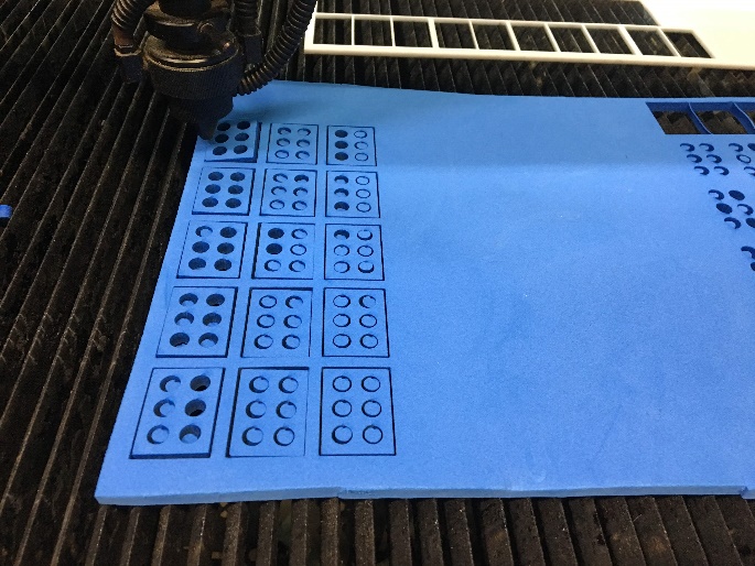
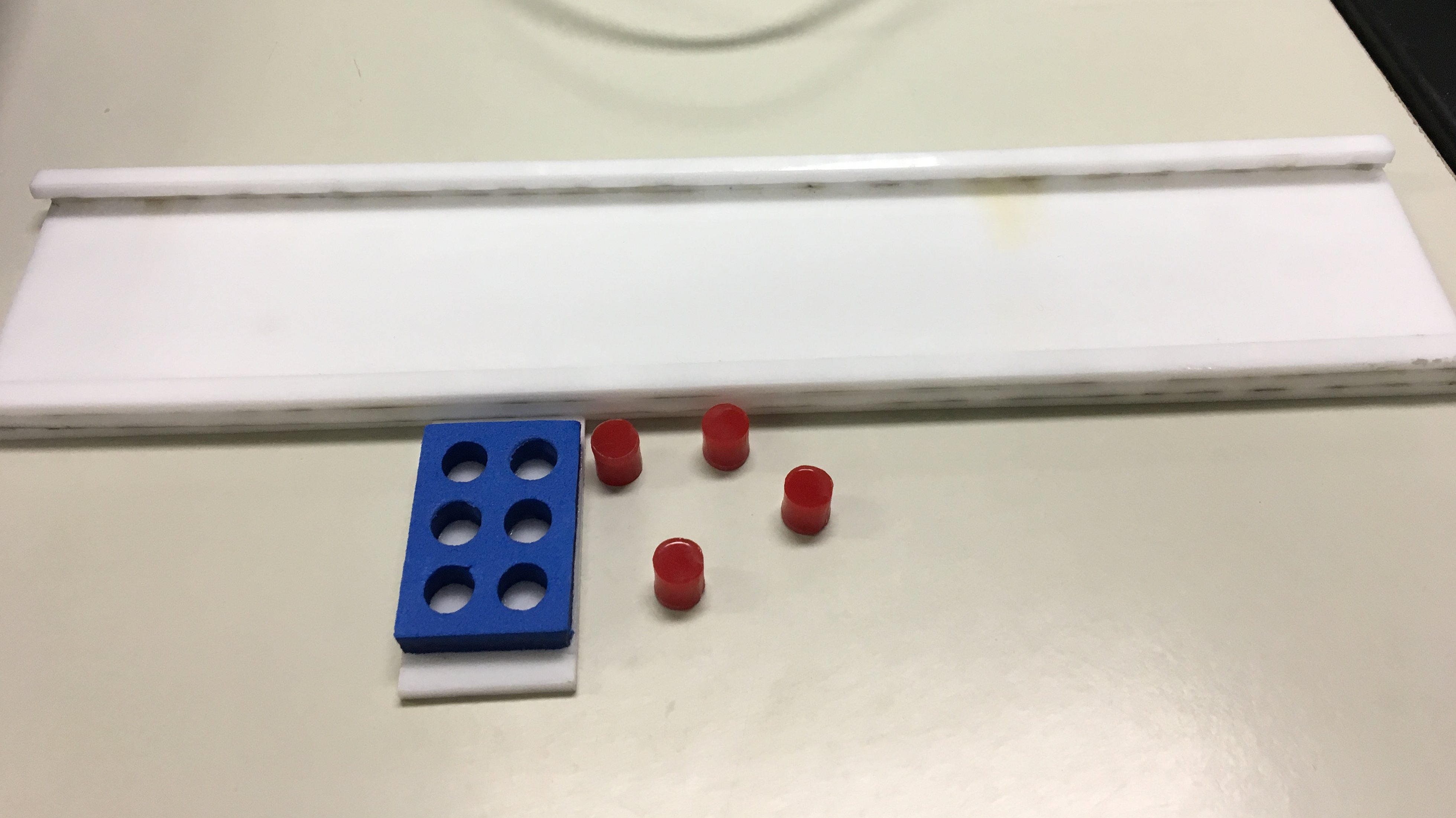
Braille cell for pin insertion that compose the representation in braille of letters, numbers and symbols:
For the confection of the cell was used a 5mm thick blue EVA (Figure 5b). As the basis of the EVA was used a 3mm thick milky white acrylic (Figure 5a).
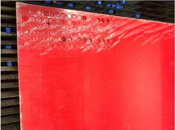
Pins that are used for insertion in the braille cells:
These pins were made in a 6mm thick red acrylic. The choice for the red color of the pins and the blue color of the braille cell are due to the ideal contrast for image processing and character recognition.
Assembling the Parts
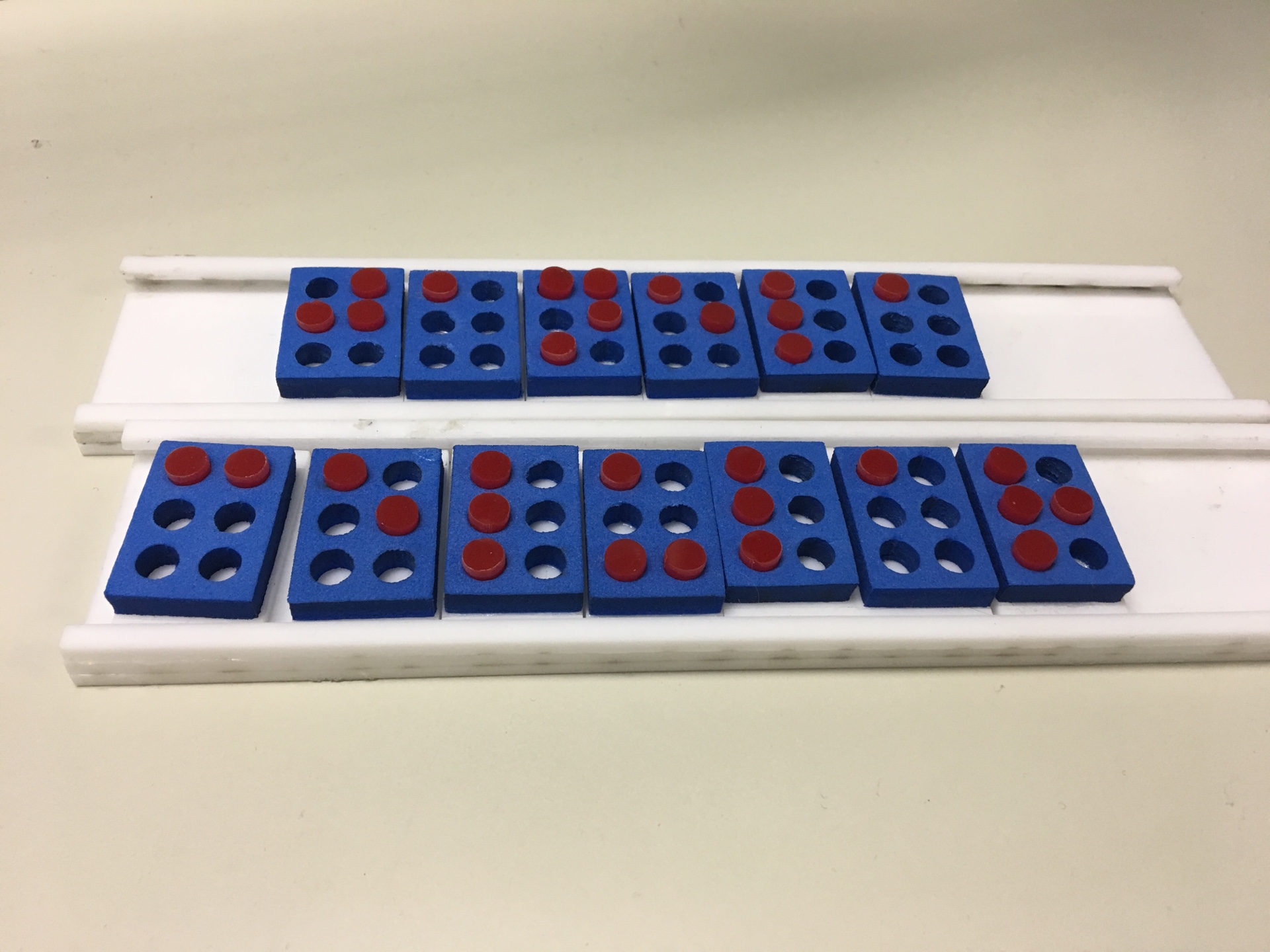
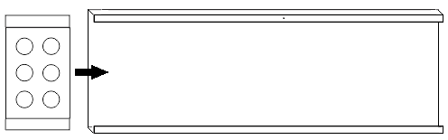
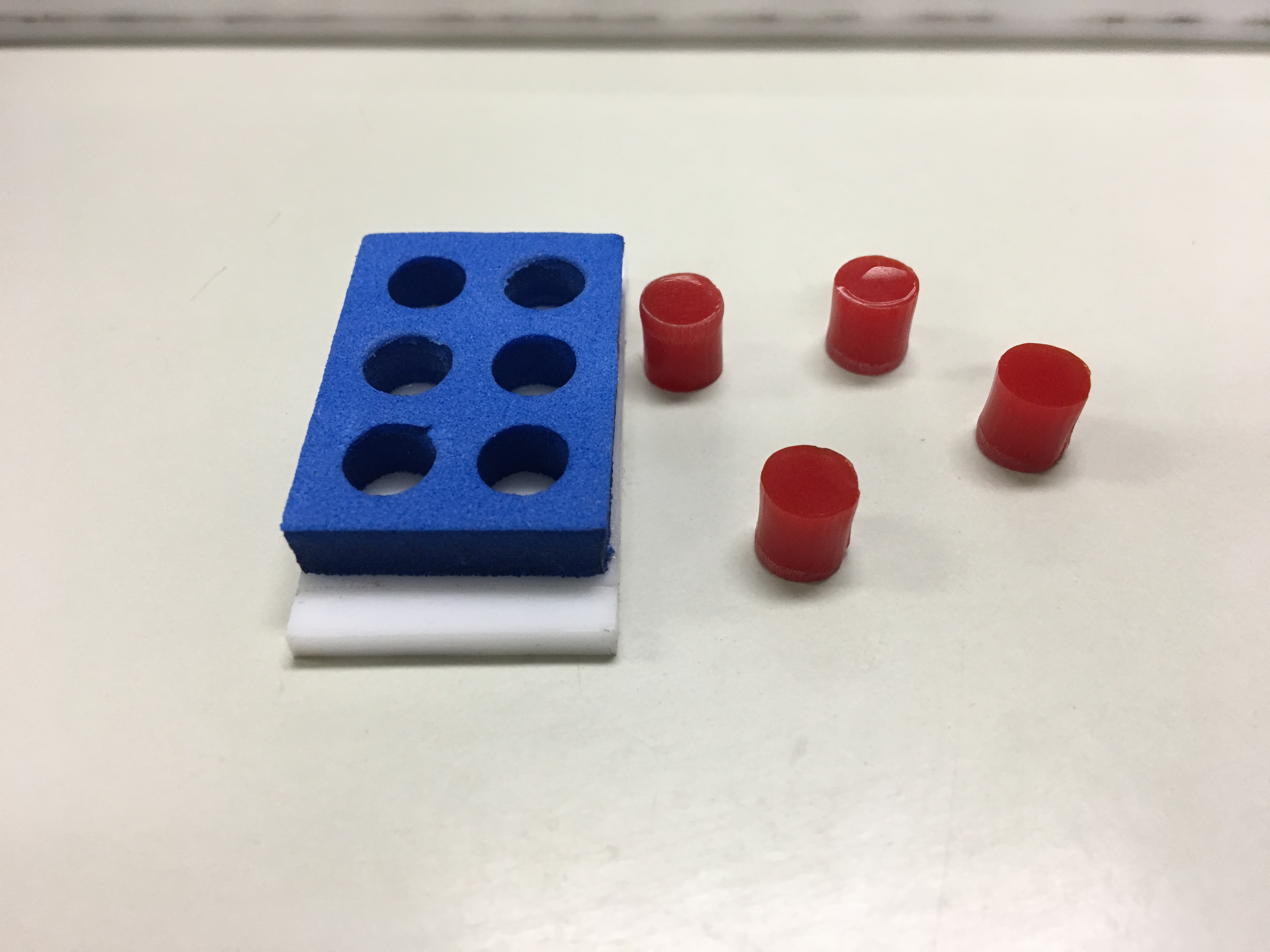
After cutting the parts in the laser cutting machine it’s possible to assemble the fixation panel and the braille cells. The EVA braille cell was glued in the white acrylic part (Figure 8). For the panels was made some kind of fitting in order that the cells could slip through the fixation panel and that it could also be easily organized.
The result after the fixation panel and the braille cell was assembled is shown below:
Final result!!