Building Your Donnie Robot
Introduction
This manual has all files required to understand how to build the Donnie robot. It explains how to print the Donnie’s body with a 3D printer and manufacture the necessary boards. It also tells you the operation of the firmware and teaches you how to assembly the parts.
Required Material
Donnie requires about 500g of PLA. We use PLA because its low retraction factor in large pieces.
Production Phase
- The 3D printer requires the stl files, in the stl_files folder.
- We use Slicer (1.2.9) to slice and 3d printing the robot. We use the following configs on slicer:
- Infill: 20%;
- Layer height: 0.3mm;
- Without support (parts that need support have it in the model).
Modifying Donnie’s Body
We used the Solidworks 2014 to model the robot. All the source files are in the solidworks directory.
Visualization
You can visualize the 3D PDF files with Adobe Reader 9 or above. You just need to click in “Enable 3D View” when open the 3D PDF.
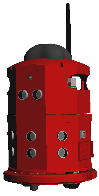
Meet Donnie !!!
Assembly the Arduino Part
Donnie’s PCB
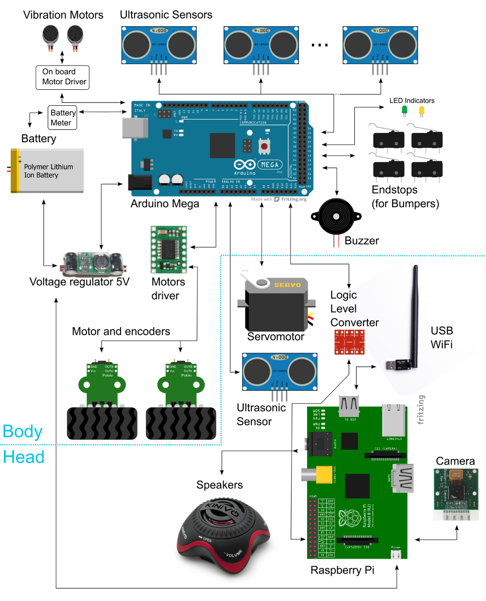
The repository has all files related to Donnie’s hardware (PCB design, schematics, eletrical diagrams, gerber files, BOM files). Donnie has two daugther boards (or ‘shields’). One for the Arduino Mega and the other for the Raspberry Pi.
Manufacturing the boards
Send the Gerber for manufacturing
If you just want to manufacture these boards as they are, we recommend the following steps:
- Send the Gerber ZIP files (arduino-shield and raspberrypi-shield) to manufacture to Seeedstudio. You should use the following tutorial Fusion PCB Order Submission Guidelines
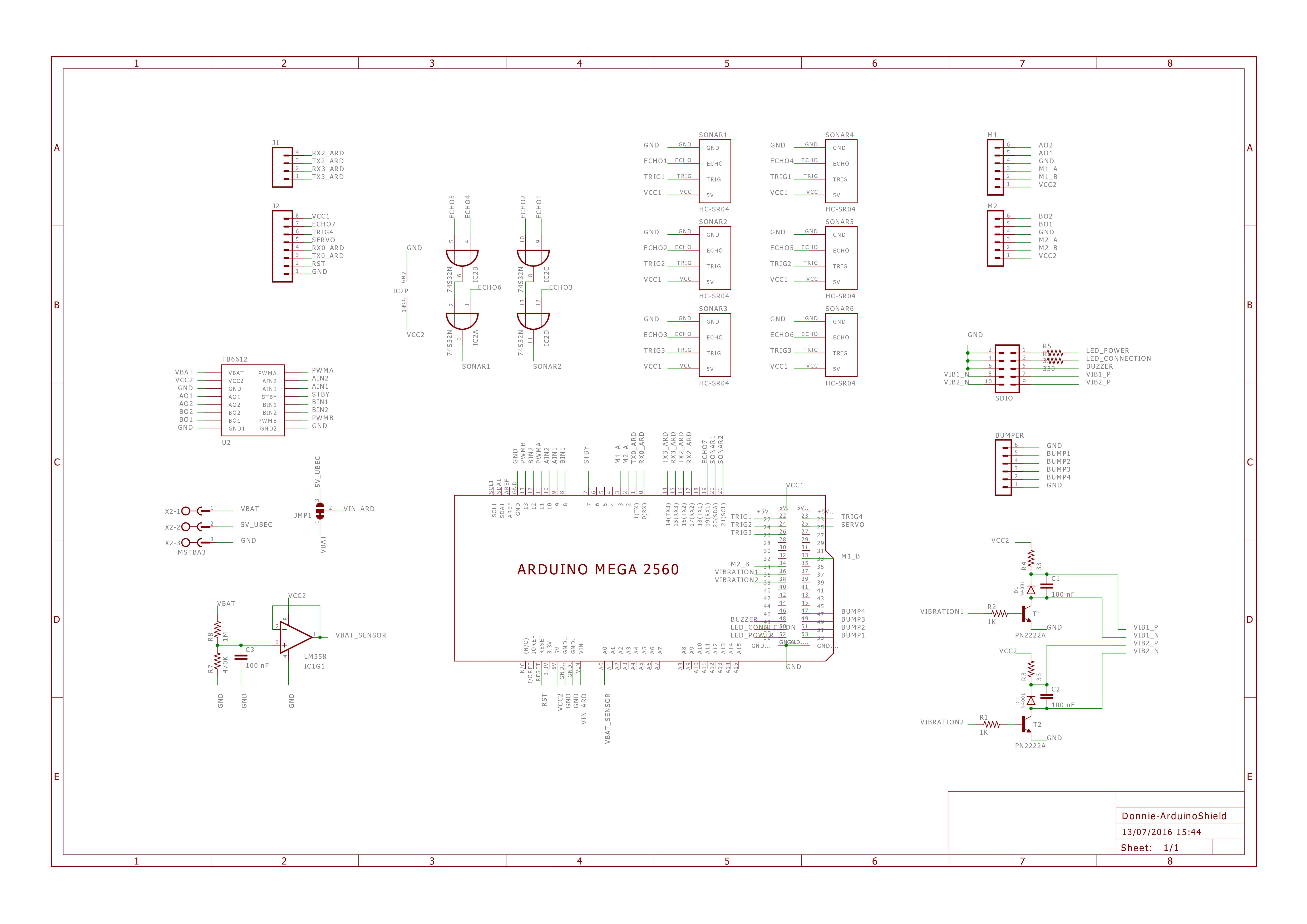
Arduino Shield
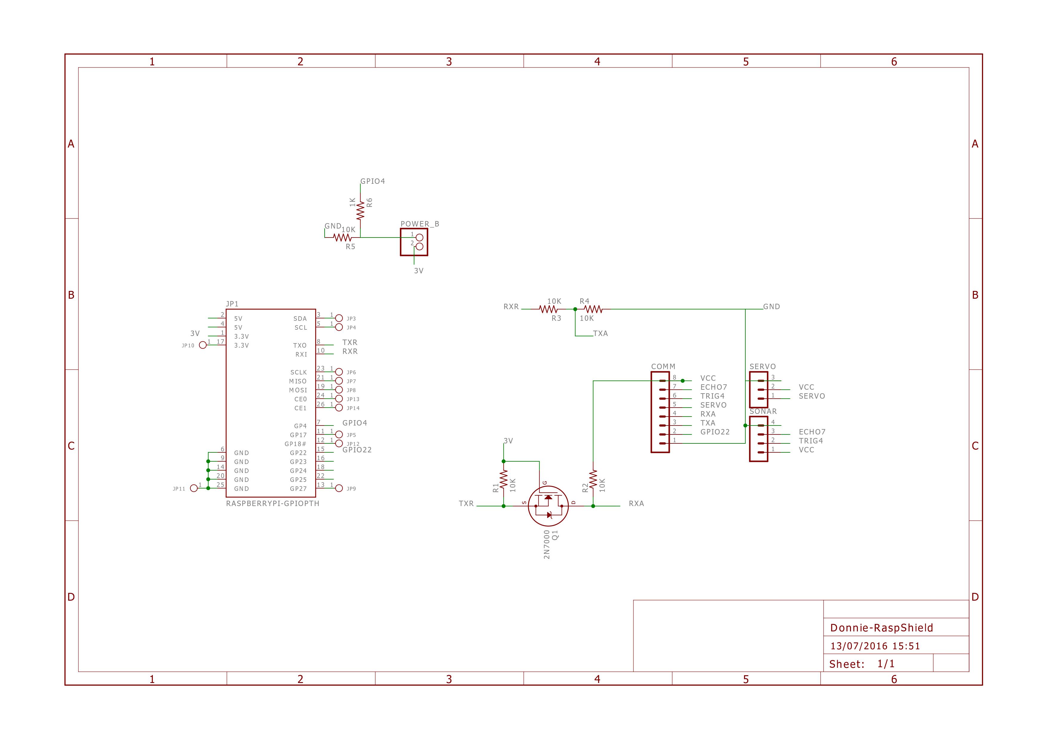
Raspberry Pi Shield
Assembly
After you receive the PCBs, then follow these steps to assemble the boards:
- First of all, separe and buy the components indicated in BOM file (arduino-shield and raspberrypi-shield);
- Print the PDF schemmatic and BOM file;
- Place and weld the componnects in the PCB with the BOM’s indicated PART.
Change the PCB Design
If you want to change the PCB design, we recommend to use Eagle version XYZ.